What a layer mapping is
In a CAD drawing, a layer carries meaning by convention: this layer is for heavy cut lines, that one for notes, another for insulation hatching. Revit does not use layers in the same way. In a drafting view, graphic meaning comes from types: line styles control weight, color and pattern of detail lines; text types control font and size; filled region types control fill patterns and their boundaries.
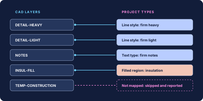
A layer mapping is a table that connects the two worlds. For every CAD layer you expect to meet, it records which Revit type that content should become, or that the content should be skipped. It turns a thousand small judgment calls into one reviewed decision.
Why it matters
- Consistency. Two people migrating similar details will produce similar results, because the decision is not theirs to remake each time.
- Template hygiene. When every layer has a target that already exists in your template, migration does not invent new line styles named after old layers.
- Reviewability. A reviewer can check the mapping once instead of discovering the same issue in fifty details.
- Reuse. The same mapping can be reused across projects and batches, and improved as you learn.
Step 1: Inventory the layers you actually meet
Start from real drawings, not just the written CAD standard. Collect a representative set of detail files and list every layer that appears, with a note of what content it carries. You will usually find three groups:
- Standard layers that follow your CAD naming convention, perhaps based on the United States National CAD Standard pattern of discipline code and major group, such as an architectural detail layer.
- Legacy variants from older standards or from consultants, which mean the same thing as a standard layer under a different name.
- Junk layers: construction geometry, viewport layers, "Layer1" and other content that should never travel.
Note which layers are used inconsistently. A layer that holds both heavy outlines and light hatching in different drawings cannot be mapped cleanly, and that needs fixing at the source or handling by exception.
Step 2: Define the Revit targets first
The mapping can only point to types that exist. Before filling in the table, confirm your template's:
- Line styles, each with a clear purpose such as cut outline, profile, light detail, hidden or centerline.
- Text types for general notes, keynotes and titles.
- Filled region types for the materials your details show, with a deliberate choice of foreground and background patterns.
Name the targets so their purpose is obvious. A line style called "Detail - Heavy" tells the next person more than "LS-03". The naming conventions guide covers this in more depth.
Resist the urge to create a Revit type for every CAD layer. CAD standards often carry more distinctions than a printed detail needs. Many layers will map to the same line style, and that is the point: the mapping is where you simplify.
Step 3: Build the mapping table
A useful mapping table has a few more columns than "from" and "to":
| CAD layer | Content | Revit target kind | Revit target | Notes |
|---|---|---|---|---|
| DETAIL-HEAVY | Cut outlines | Line style | Detail - Heavy | Standard layer |
| OLD-DET-THICK | Cut outlines | Line style | Detail - Heavy | Legacy variant |
| NOTES | General notes | Text type | Note - Standard | Single-line text only |
| INSUL-FILL | Insulation zones | Filled region type | Insulation - Batt | Closed boundaries only |
| TEMP-CONSTRUCTION | Construction lines | Skip | None | Never migrate |
Add columns for status (proposed, approved), the reviewer and the date if you want the mapping to double as an audit trail. Keep it in a format the whole team can open: a spreadsheet works well.
Step 4: Handle the awkward cases
Object-level overrides
CAD objects can override their layer's color, linetype or lineweight. A layer mapping assumes content follows its layer. Find drawings where overrides carry meaning and either fix them at the source, by moving the objects to the right layer, or accept that those details need a manual pass.
One layer, several meanings
If a layer was used for different purposes in different drawings, no single target is right. Split it at the source where you can. Otherwise, map it to the most common meaning and flag those drawings for review.
Hatches and fills
CAD hatches and Revit filled regions are related but not equivalent. Decide which hatch layers should become filled regions, which patterns correspond, and what to do with hatches whose boundaries are not closed. Some converters, including Codex today, do not convert hatches at all; they create filled regions only from closed boundaries on layers mapped to a filled region type.
Text
Map text by purpose, not by font. If the CAD standard has several text styles that all mean "general note", they can share one text type. Multi-line text and text with inline formatting may need special handling depending on your route.
Blocks, dimensions and symbols
These rarely map one-to-one. A dimension should usually be recreated as a Revit dimension so it stays associative; a block for a fixing or component may be better replaced with a Revit detail component. Record these as "recreate natively" rather than forcing a line-style mapping.
Step 5: Make skips explicit
A good mapping says not only what converts, but what does not. Unmapped layers should be a deliberate decision with a reason: construction geometry, viewport frames, out-of-date notes. When a migration tool or method skips content, the people reviewing the result need to know whether that skip was intended.
Tools that report what they skipped make this much easier. Codex, for example, previews entity counts and skip diagnostics before converting, and labels a result that left entities behind as complete with skips, so a reviewer can tell an intended skip from an unexpected one. Whatever your method, keep a list of intended skips next to the mapping.
Step 6: Test on real samples
Before approving the mapping, run it against a small, varied sample of details in a test project. For each one, check:
- Did every visible element land on the expected type?
- Did anything disappear that should have stayed?
- Does the printed result match the intended line weight hierarchy?
- Did any new, non-standard types appear in the project?
Each surprise is either a mapping fix or a source-cleanup rule. Update the table and test again. Two or three rounds on a varied sample usually reveal the important gaps.
Version and govern the mapping
Treat the mapping as a controlled standard document:
- Give it a version number and a change log.
- Name one owner who approves changes.
- When the template changes, for example a line style is renamed, update the mapping in the same change.
- Keep project-specific mappings separate from the firm default, and record why they differ.
- Review it when you take on a significant new source, such as a consultant's details or an acquired practice's library.
Putting the mapping to work
A written mapping is useful even if every detail is redrawn by hand: it tells the person redrawing which types to use. It becomes more valuable when a tool applies it automatically.
Codex uses an explicit mapping of this kind. In its Create Mapping dialog, each DXF layer is mapped to one of the project's existing line styles, text types or filled region types, and the mapping can be reused across projects so the same layers convert the same way each time. See how Codex works for its current entity coverage.
If you would rather start from a structured template than a blank spreadsheet, the draft CAD Layer to Revit Standards Mapping Workbook provides one. Either way, the thinking in this guide is what makes the mapping trustworthy.
Mapping checklist
- Layer inventory taken from real drawings, including legacy variants.
- Revit target types defined and named in the template.
- Every layer has a target or an explicit skip with a reason.
- Overrides, mixed-use layers, hatches, text and blocks handled by rule.
- Tested on a varied sample; surprises resolved.
- Versioned, owned and linked to template changes.